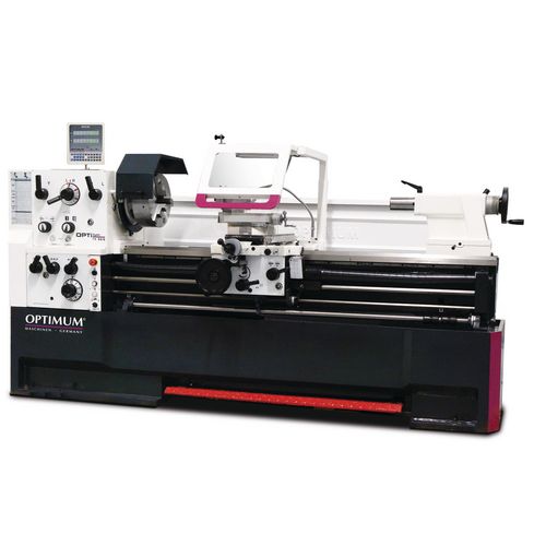
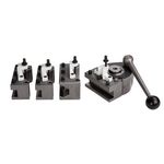
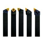
- Hardened and ground Z-axis guideway
- Guaranteed concentricity of the spindle nose ≤ 0.015 mm
- Spindle holder Camlock DIN ISO 702-2 No. 8
- Lead screw cover
- Precisely machined slide
- All guides can be adjusted using gibs
- Right/left rotation on bed slide switchable via switching spindle
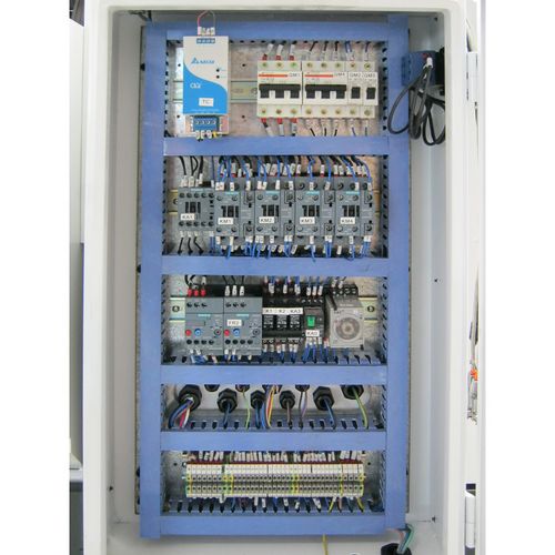
- Two-channel safety electronics
- Central lubrication in the bed slide
- Upper slide adjustment range ± 90
- Main spindle runs in oil bath
- Shafts and wheels running in oil bath
- Gear wheels smooth-running, hardened, ground and mounted with 2 adjustable precision tapered roller bearings
- Switch with life cycle calculation, tested in accordance with EN ISO 13849
- Handwheels with adjustable fine scaling 0.04 / 0.02 mm
- Safety handwheels with disengagement function in accordance with EN23125 in the X and Z axes
- Gear wheels and shafts hardened and ground, running in an oil bath in precision bearings
- Clearly arranged selector lever for switching the feed speeds
- Closed design of the high-speed feed gearbox
- Emergency stop impact switch, motor protection switch, lockable main switch
- Emergency stop device with foot actuation
- Tailstock for taper turning ± 10 mm adjustable
- Tailstock quill and handwheel with adjustable fine scaling 0.025 mm. Quick, easy and tool-free adjustment by means of clamping lever
- Energy chain for gentle cable and hose guidance
- Heavily ribbed prism bed, induction-hardened and precision-ground from gray cast iron
- Coolant device with separate coolant tank with level indicator and oil separator; easy and complete emptying and cleaning in accordance with DIN
- Adjustable scale of the thread gauge
| Cooling lubricant system |
|---|
| Coolant pump output | 125 W |
| Dimensions and weights |
|---|
| Length approx. | 4450 mm |
| Width/depth approx. | 1150 mm |
| Height approx. | 1650 mm |
| Weight approx. | 3000 kg |
| Electrical Data |
|---|
| Drive motor output | 7,5 kW |
| Total rated value | 8.5 kW |
| Supply voltage | 400 V |
| Mains frequency | 50 Hz |
| Feed |
|---|
| Longitudinal feed range | 0,059 – 1,646 mm/rev |
| Number of longitudinal feeds | 35 |
| Flat feed range | 0,020 – 0,573 mm/rev |
| Number of flat feeds | 35 |
| Pitches |
|---|
| Metric pitch | 0,2 – 14 mm/rev |
| Number of metric pitches | 47 |
| Imperial pitch | 112 – 2 Gg/1" |
| Number of imperial pitches | 60 |
| Diametrical pitch | 4 – 112 DPI |
| Number of diametrical pitches | 50 |
| Modular thread pitch | 0,1 – 7 mm/rev |
| Number of modular thread pitches | 34 |
| Speed range |
|---|
| Number of gears | 12 |
| Speed range | 25 – 1600 min¯¹ |
| Spindle |
|---|
| Spindle chuck | Camlock DIN ISO 702-2 No. 8 |
| Spindle bore/rod passage diameter | 80 mm |
| Tool holder max. chuck height | 25 mm |
| Spindle cone | MT 7 |
| Tailstock |
|---|
| Chuck | MK 5 |
| Quill stroke | 180 mm |
| Quill diameter | 75 mm |
| Travel |
|---|
| Travel upper slide | 130 mm |
| Travel cross slide | 316 mm |
| Travel carriage saddle | 2710 mm |
| Work areas |
|---|
| Max. height | 280 mm |
| Max. width | 2910 mm |
| Swing diameter above machine bed | 560 mm |
| Swing diameter in bed bridge | 790 mm |
| Swing diameter above planing slide | 355 mm |
| Turning length in bed bridge | 170 mm |
| Bed width | 350 mm |
Unit: pc(s).
Packaging unit: 1
- Fixed bezel passage max. Ø 165 mm
- Running bezel passage max. Ø 95 mm
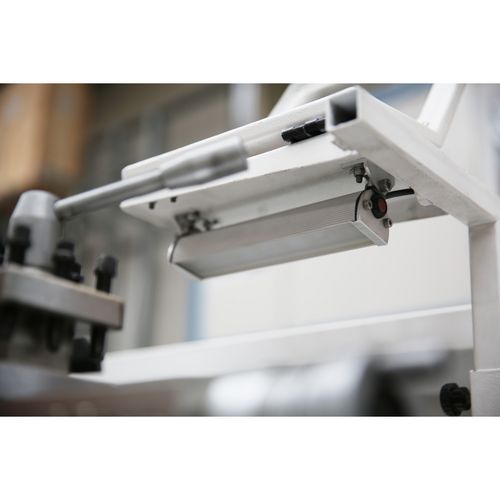
- LED machine light
- TH 5615D-TH 5630D: Reduction sleeve MK 7 / MK 5
- TH 5620V: Reduction sleeve Ø 113 mm / MK 5
- Fixed centering point MK 5
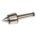
- Fixed and revolving centering point MK 5
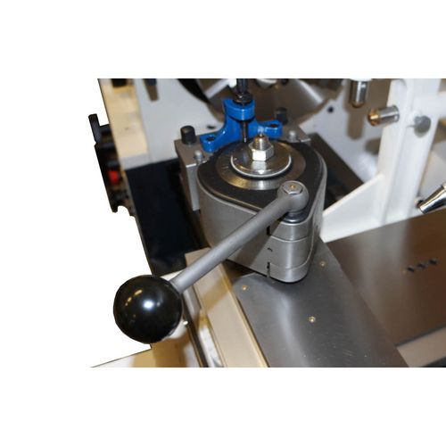
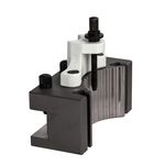
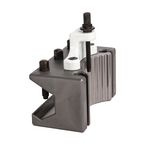
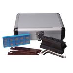
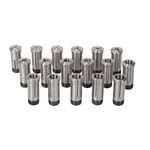
- Quick change steel holder 7-C
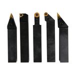
- Steel holder 32 x 150 type D for square chisels
- Threading gauge
- Initial machine filling with quality oil
- Change gear set
- operating tool
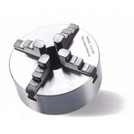
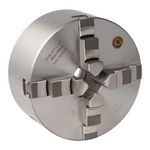
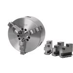
Do not forget the lathe chuck!
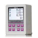
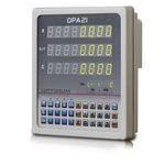
| Digital position indicator | DPA 31 Plus |

